
In precision analog design, the gap between theoretical simulation and real-world noise often dictates project success or failure. The MAX74811 auto-zero amplifier closes this gap with a 2.5 MHz gain bandwidth product and rail-to-rail I/O swing. This breakdown dissects the MAX74811 datasheet to reveal how its specific performance metrics can stabilize your signal chain in noisy environments.
Core Architecture: Auto-Zero Amplifier Fundamentals
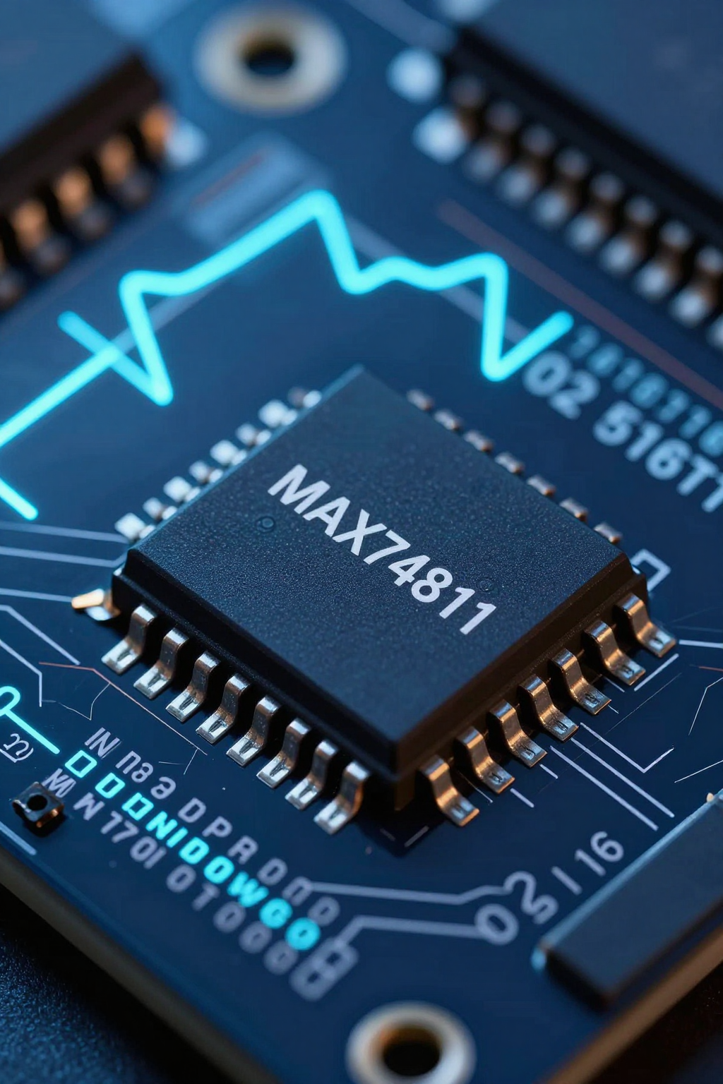
You must understand that traditional op-amps suffer from offset voltage drift over time and temperature. The MAX74811 addresses this through an internal chopping mechanism. This topology continuously corrects input offset, maintaining microvolt-level stability without external calibration circuits.
Understanding Zero-Drift Topology
The core advantage lies in eliminating DC errors. Unlike standard amplifiers where offset accumulates, the zero-drift architecture samples and corrects the error at high frequencies. You will observe significantly reduced long-term drift, which is critical for sensor interfaces requiring high accuracy over extended periods.
Rail-to-Rail Input/Output (RRI/RRO) Mechanics
Maximizing dynamic range in low-voltage systems requires full-swing capability. The RRI/RRO design allows you to utilize the entire supply voltage range. For single-supply applications up to 6V, this ensures minimal headroom loss, preserving signal integrity even when operating near the supply rails.
Critical Performance Metrics Analysis
Evaluating speed versus power consumption is essential for your design trade-offs. The device balances a robust 2.5 MHz Gain Bandwidth Product (GBP) with a 1 V/µs slew rate. These figures determine how quickly your system responds to step changes in input signals.
| Parameter | Typical Value | Unit | Impact |
|---|---|---|---|
| Gain Bandwidth Product | 2.5 | MHz | Determines small-signal frequency response limit. |
| Slew Rate | 1.0 | V/µs | Limits large-signal transient response speed. |
| Input Offset Voltage | < 5 | µV | Critical for DC accuracy in sensor front-ends. |
| Quiescent Current | 350 | µA | Balances thermal management and noise floor. |
Bandwidth and Slew Rate Trade-offs
You should calculate settling times carefully in high-speed data acquisition loops. While the GBP supports moderate frequency response, the slew rate limits large-signal performance. Ensure your closed-loop gain configuration does not push the amplifier into saturation delays that compromise measurement accuracy.
Noise Floor and Power Consumption
Input-referred noise density directly impacts the resolution of small signals. Correlate quiescent current per channel with thermal management strategies, especially in compact MSOP packages. Lower power consumption reduces heat generation, but you must verify that the noise floor remains acceptable for your specific application requirements.
Application-Specific Design Guidelines
Implementing these devices requires attention to physical layout and peripheral circuitry. Proper decoupling and grounding techniques are non-negotiable for achieving the specified performance metrics in real-world conditions.
Sensor Signal Conditioning Best Practices
When amplifying thermocouples or strain gauges, leverage the auto-zero feature to eliminate baseline errors. Recommend filtering techniques to mitigate aliasing effects introduced by the chopping action. Use low-pass filters matched to your signal bandwidth to ensure clean output data.
PCB Layout and Decoupling Strategies
Place bypass capacitors close to the power pins to minimize ground bounce. Address thermal coupling effects between the two channels within the 8-pin MSOP package. Isolate sensitive analog traces from digital switching lines to prevent crosstalk that could degrade the common-mode rejection ratio.
Key Takeaways
- The MAX74811 datasheet highlights zero-drift topology for microvolt-level offset stability.
- Rail-to-rail I/O maximizes dynamic range in low-voltage single-supply designs.
- Balance the 2.5 MHz GBP and 1 V/µs slew rate for optimal settling times.
- Proper PCB layout and decoupling are critical for maintaining low noise floors.