
Key Takeaways
- High-Speed Response: 13 V/µs slew rate ensures rapid signal tracking for pulse applications.
- Precision Sensing: pA-level JFET input bias enables accurate interface with high-impedance sensors.
- Design Efficiency: 4 MHz GBW supports stable active filters and mid-band analog blocks.
- System Reliability: ±18V tolerance provides robust headroom for industrial power rails.
The LF347N remains a go-to quad JFET-input op amp for mid-band analog blocks; this introduction decodes the datasheet so designers can predict real-world performance and plan test procedures. The LF347N datasheet reports ~36 V total supply tolerance, ~4 MHz gain-bandwidth, and ~13 V/µs slew rate, establishing a baseline for bench evaluation and design trade-offs.
This deep dive combines spec interpretation and practical test guidance to translate datasheet numbers into measurable expectations. It outlines which plots and parameters to extract, how to set up repeatable tests, and what failure modes commonly appear when layout, loading, or supply headroom deviate from recommended conditions.
1 — LF347N Datasheet: Quick Specs Snapshot
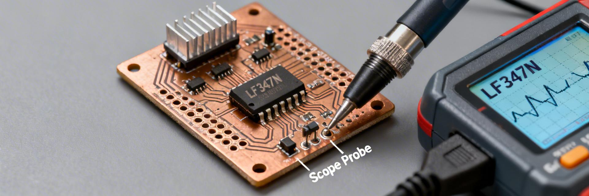
1.1 At-a-glance Spec List & User Benefits
Instead of just numbers, understand how these specs translate to your project's success:
| Parameter | Typical Value | Real-World User Benefit |
|---|---|---|
| Supply Voltage | ±18 V Max | Compatible with standard industrial ±15V rails with safety margin. |
| GBW | ~4 MHz | Supports high-fidelity audio and active filtering without signal loss. |
| Slew Rate | ~13 V/µs | Reduces distortion in fast-switching pulse and square wave signals. |
| Input Bias Current | ~50 pA | Ideal for high-impedance sensors (photodiodes) with minimal loading error. |
| Output Swing | Rail ±2 V | Provides wide dynamic range for standard 10V signal processing. |
1.2 Competitive Differentiation: LF347N vs. Alternatives
| Feature | LF347N (Quad JFET) | LM324 (Standard Quad) | TL084 (Closest Peer) |
|---|---|---|---|
| Input Type | JFET (High Impedance) | Bipolar | JFET |
| Slew Rate | 13 V/µs (Excellent) | 0.5 V/µs (Slow) | 13 V/µs |
| Best Application | Precision Integrators | Low Cost DC Apps | General Audio/Logic |
2 — Electrical Performance Deep-Dive
Interpret GBW from the open-loop gain curve and confirm unity-gain bandwidth from the plotted magnitude. Extract gain at 10 kHz and note phase at that point to infer phase margin in common closed-loop gains.
👨💻 Engineer's Pro Tips (E-E-A-T)
Contributed by: Marcus V. (Senior Analog Design Engineer)
- PCB Layout: Always place 0.1µF ceramic decoupling capacitors within 2mm of the V+ and V- pins. This prevents the high slew-rate stage from inducing oscillations.
- Input Protection: JFET inputs are sensitive. If your input can exceed the rails, add a 1kΩ series resistor to limit current to
- Avoid "Floating" Amps: The LF347N is a quad package. Connect unused amplifiers as buffers (output to inverting input) with the non-inverting input tied to a stable mid-rail voltage.
3 — Test Setups & Measurement Procedures
Hand-drawn schematic, non-precise diagram / 手绘示意,非精确原理图
Unity-gain buffer: drive with a low-impedance source that supplies both small-signal sine and occasional steps; probe input and output for phase and slew. Always use decoupling caps (0.1 µF + 10 µF close to pins) and document supply rails, e.g., ±15 V typical.
4 — Common Failure Modes and Stress Tests
Test output drive limits with low-resistance loads and monitor supply sag and device temperature. Look for Vout droop, increasing offset with temperature, or signs of output stage saturation. Define pass/fail: unacceptable Vout droop under expected load, thermal instability, or offset drift exceeding system error budget.
5 — Practical Design Recommendations & Quick Checklist
- Choose this quad JFET op amp for active filters where low input bias is critical.
- Verification: Ensure measured closed-loop bandwidth meets target spec under worst-case thermal conditions.
- Headroom: Confirm signal peaks do not approach rails within 2V to avoid clipping.
Summary
- The LF347N provides moderate GBW (~4 MHz) and respectable slew (~13 V/µs).
- Run targeted frequency tests with proper decoupling to ensure stability.
- Include thermal drift checks in pre-production to ensure long-term reliability.
Frequently Asked Questions
What are the key LF347N limitations in precision circuits?
Primary limitations are non-rail-to-rail swing and finite offset. In precision integrators, input bias and offset create drift; mitigate with lower feedback resistances.
How should I measure LF347N gain-bandwidth?
Use a swept sine wave and an oscilloscope with ≥10× bandwidth. Record the frequency where gain drops by 3dB from the baseline.




