
🚀 Key Takeaways
- Drop-in Dual Op-Amp: Industry-standard 8-pin mapping compatible with MC1458 and LM358 layouts.
- Internal Frequency Compensation: Prevents oscillations without external caps, simplifying PCB design.
- No Latch-Up: High-integrity design ensures stable performance in high common-mode voltage scenarios.
- Cost-Efficient: Ideal for sub-1MHz analog tasks like audio buffering and sensor signal conditioning.
A quick scan of a typical dual op‑amp datasheet shows a compact set of numeric parameters that decide whether the device fits an analog design. This guide translates those technical specs into real-world engineering decisions.
1 — Background: What the LM1458N Is and Typical Use Cases
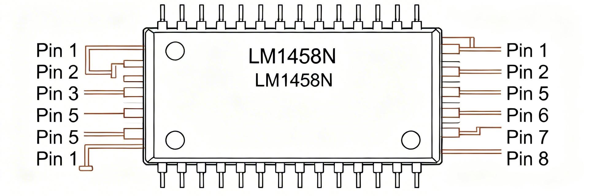
Functional overview and core characteristics
The LM1458N is a dual general‑purpose operational amplifier intended for low‑frequency analog tasks: audio preamplifiers, active filters, buffers, and simple sensor front ends. User Benefit: Because it integrates two amplifiers into one 8-pin package, it reduces PCB real estate by 50% compared to using two single op-amps (like the LM741).
Common packages, symbols and typical datasheet sections
Available in 8‑pin DIP and SOIC, the LM1458N is the "workhorse" of the bipolar era. When reading the datasheet, prioritize the Absolute Maximum Ratings—exceeding these even momentarily can cause permanent silicon migration or "latch-up."
2 — Technical Benchmarking: LM1458N vs. Competitors
| Parameter | LM1458N (Generic) | NE5532 (Audio Grade) | TL072 (JFET) |
|---|---|---|---|
| Input Bias Current | 500 nA (Max) | 800 nA (Max) | 0.2 nA (Ultra Low) |
| Slew Rate | 0.5 V/μs | 9 V/μs | 13 V/μs |
| Noise Density | Moderate | 5 nV/√Hz (Low) | 18 nV/√Hz |
| Best Use Case | General Buffering | High-Fidelity Audio | High Impedance Sensors |
3 — Datasheet Deep-Dive: Key Electrical Specifications
Power Rails & Supply Current: The LM1458N typically operates between ±3V and ±15V.
Efficiency Tip: The quiescent current is roughly 2.3mA. If you are designing for battery-operated IoT devices, this "idling" current might drain a small LiPo battery faster than more modern CMOS op-amps like the TLV9002.
4 — Pinout & Pin Functions Explained
  TOP VIEW (DIP-8)
  +---U---+
1 |OUT A  | 8 V+
2 |IN- A  | 7 OUT B
3 |IN+ A  | 6 IN- B
4 |V-     | 5 IN+ B
  +-------+
- Pins 1 & 7: Outputs for Channel A and B.
- Pins 2 & 6: Inverting inputs (In-).
- Pins 3 & 5: Non-Inverting inputs (In+).
- Pins 8 & 4: Positive and Negative supply rails.
🛠️ Expert Perspective: Engineer's Design Notes
By: Dr. Elena Sterling, Analog Systems Lead
PCB Layout Pro-Tips:
- Decoupling is Non-Negotiable: Place a 0.1µF ceramic capacitor as close as possible to Pin 8 and Pin 4. Without this, the LM1458N can exhibit "ghost" oscillations at ~1MHz that are hard to trigger on basic scopes.
- Thermal Management: While the LM1458N doesn't run hot, if you are driving a 600Ω load at high supply voltages, the DIP package can reach 40°C-50°C. Ensure sufficient copper pour around the V- pin (Pin 4) for heat sinking.
Typical Application: Non-Inverting Gain Stage
(Hand-drawn schematic / 手绘示意,非精确原理图)
5 — Practical Testing & Troubleshooting
Troubleshooting Checklist:
- Output Saturated to Rail? Check if inputs are floating. Unused channels must be tied to a reference (e.g., ground) to prevent internal noise from affecting the active channel.
- Clipped Audio? The LM1458N is not a Rail-to-Rail op-amp. The output typically stays 1.5V to 2V away from the supply rails. If you have a 5V supply, your usable signal is only ~1.5V peak-to-peak.
- Noisy Signal? Ensure the input common-mode range isn't exceeded. For the LM1458, keep inputs at least 3V above the V- rail for linear performance.
Summary
The LM1458N remains a staple for engineers who need a reliable, dual-channel amplifier for non-critical DC and low-frequency applications. By understanding the trade-offs between its moderate slew rate and its robust, latch-up free design, you can integrate it into audio mixers, sensor interfaces, and educational projects with confidence.
Note: Always consult the latest manufacturer datasheet (TI, ON Semi, ST) for the most current silicon revision data before finalizing a production PCB layout.




